Every software develop has their own process for optimization, making stuff go faster. Generally you would settle on finding the correct algorithm then perhaps turn to I/O related stuff and last to cache coherency. We normally stop once some kind of target criteria is met.
There is however situations which require you turn go the extra mile. To dust off those assembler skills. It could be you can use intresnics from C/C++ or your data structures make certain things obvious for you but not the compiler. Or you are targetting an older platform, where perhaps the compiler is rather rudimentary.
I recently had to go the extra mile and deep dive in to assembler and lord was I in fore a struggle. I took quite a while before I found a way that really made my optimization process so much quicker. Here is how I do it.
- Ensure the algorithm is good - this is key, there are always more than one way to achieve the same goal!
- Once implemented, implement another version with very simple statements/expressions.
- Transform the simplified version into assembler like statements. Use ONLY variables matching the amount of registers you have available.
- Convert the transformed code to assembler - this should almost be a line-by-line mapping.
Example
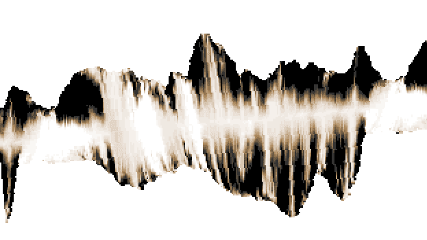
Picture below shows what we want to optimize. Essentially this is a raycasting effect, target platform is an Amiga with a Motorola 68060 processor. Target framerate is 25fps.
Basically the effect will raycast over a height-map and then render span’s when the height difference between two points is greater than zero. The most basic version is a landscape but you can also wrap it around other shapes. In this case we wrap it around a cylinder.
There are two things that makes this a bit peculiar.
- We want allow the cylinder to rotate around the Z-axis
- We want it lightsourced
Step 1
The first approach I took to this was to skip the rotation and just have the light.
static int castRay_cylinder_opt(GOA_PIXMAP8 *target, int x, int y, int x_step, float yrot, float u, float v) {
    int h;
    float hraw;
    GOA_VECTOR p;
    GOA_VECTOR normal;
    GOA_VECTOR up={0,1,0};
    GOA_VECTOR lightv={0,0,1};

    int h_prev = 0;//target->height;

    uint8_t *scanline = &target->image[y * target->width + x];

    int dh;

    GOA_VECTOR vh, vhprev;

    goa_vector_set(&vhprev,0.5,0,1);

    for(int i=0;i<STEPS;i++) {

        hraw = 2.0 * (float)terrainHeightAt(u,v);
        h = project(hraw, i);

        if ((h > h_prev) && (h>0)) {

            uint8_t col = terrainColAt(u,v);
            uint8_t light = lightAt(i, u,v);

            col = lighttable[col * LIGHT_STEPS + light];

            // This is the actual pixel plotting loop, but without
            // proper shading and not much 'fun'...
            while(h_prev != h) {
                *scanline = col;
                scanline+=x_step;
                h_prev++;
            }
            // end pixel plotting loop
        }

        u += x_step;
    }

    return FALSE;
}
This version does not rotate around the z-axis, and has not shading. Thus it is a bare-bone version. The stuff within the while loop is the actual pixel plotting loop.
Step 2
Let’s add light and z-rotate, we get this:
    while(cyl->h_prev != cyl->h) {
        x = goa_fix12_to_int(cyl->xp);
        y = goa_fix12_to_int(cyl->yp);

        if ((x>0) && (x<target->width-1)) {
            c = ltab[fix_to_int(cyl->l)];

            // this will output two pixels - otherwise we will have holes due to interpolation errors
            scanline = &target->image[target->width * y];
            scanline[x] = c;
            scanline[x+1] = c;
        }

        cyl->xp += cyl->x_step;
        cyl->yp += cyl->y_step;
        cyl->l += cyl->l_step;
        cyl->h_prev++;
    }
Each pixel requires that we interpolate three values (x/y for screen and l for light).
As I would have to supply way too many arguments to the interpolation function I have gathered them in a structure and simply pass the pointer to said struct down to the interpolator.
Step 3
Once I have a fairly clean routine I start the optimization process by translating the C code to what I call C-Asm. This is more or less a C version with simple statement mimicing assembler instructions. I also replace all variables with register alikes.
This would give something like this:
    // Changed to do/while - because more similar to asm...
    do {
        d0 = a2->xp;
        d1 = a2->yp;
        d0 = d0 >> 12;
        d1 = d1 >> 12;

        // Skip Y-Clip since we allocate a larger buffer than needed and hence can write outside
        // Buffer has 48 scanlines extra above/below

        // Could potentially skip this...
        if ((d0>0) && (d0<a0->width-1)) {
            d3 = a2->l;
            d1 = d1 * a0->width;
            d3 = d3 >> 7;
            //d2 = a1[fix_to_int(a2->l)];
            a4 = &a3[d1];
            d2 = a1[d3];

            // this will output two pixels - otherwise we will have holes due to interpolation errors
            a4[d0] = d2;
            a4[d0+1] = d2;
        }
        d0 = a2->x_step;
        d1 = a2->y_step;
        d3 = a2->l_step;

        a2->xp += d0;
        a2->yp += d1;
        a2->l += d3;
        d4--;
    } while(d4);
Now, this can trivally be converted to pure assembler. It is also much easier to semi pipeline the instructions in C vs. Assembler.
